
This test can be explained first using the axonometric view in Figure 1. The test geometry consists of 4 single height spaces where one (1) of the spaces shares an adjacent interior wall with three (3) identical single height spaces.
The typical use case would be one where the user has defined the one (1) space (i.e. - Space_0_0) first as a standalone zone and then draws (in no particular order) the other three (3). When exported to gbXML, it is expected that the single wall separating Space_0_0 from the others is broken into five (5) separate walls, three (3) of which are interior walls and two (2) of which are exterior walls, as indicated in Figure 3. In addition, this test ensures that the remaining surfaces are properly assigned to their respective wall, floor, or roof surface type.
It should be noted that there are windows (Openings in gbXML terminology) that should be drawn for this test. The absolute position of the windows is not critical, but the overall area should be approximately 95% of the wall area.
It is very important that the space names in your certification file must adhere to the naming convention shown in Figures 1, 2, and 3. If the spaces are not named appropriately, then the validator software will not be able to achieve a Passing Score.
The remaining figures can be used to find actual coordinates and dimensions, where the dimensions are drawn at the centerline of the surface, per gbXML convention. Dimensions in the east-west direction are the X-dimension, and in the north-south are the Y-dimension. Z is in the final direction (up and down), as shown in Figure 3.
Please note that dimensions are in meters that these surfaces have no inherent thickness, which is common for a certain subset of geometry creation tools. If you are having trouble drawing a figure such as this in your CAD or BIM tool because of restrictions preventing zero thickness, please contact gbXML for assistance if the validator software is not passing your test.
Figure 1
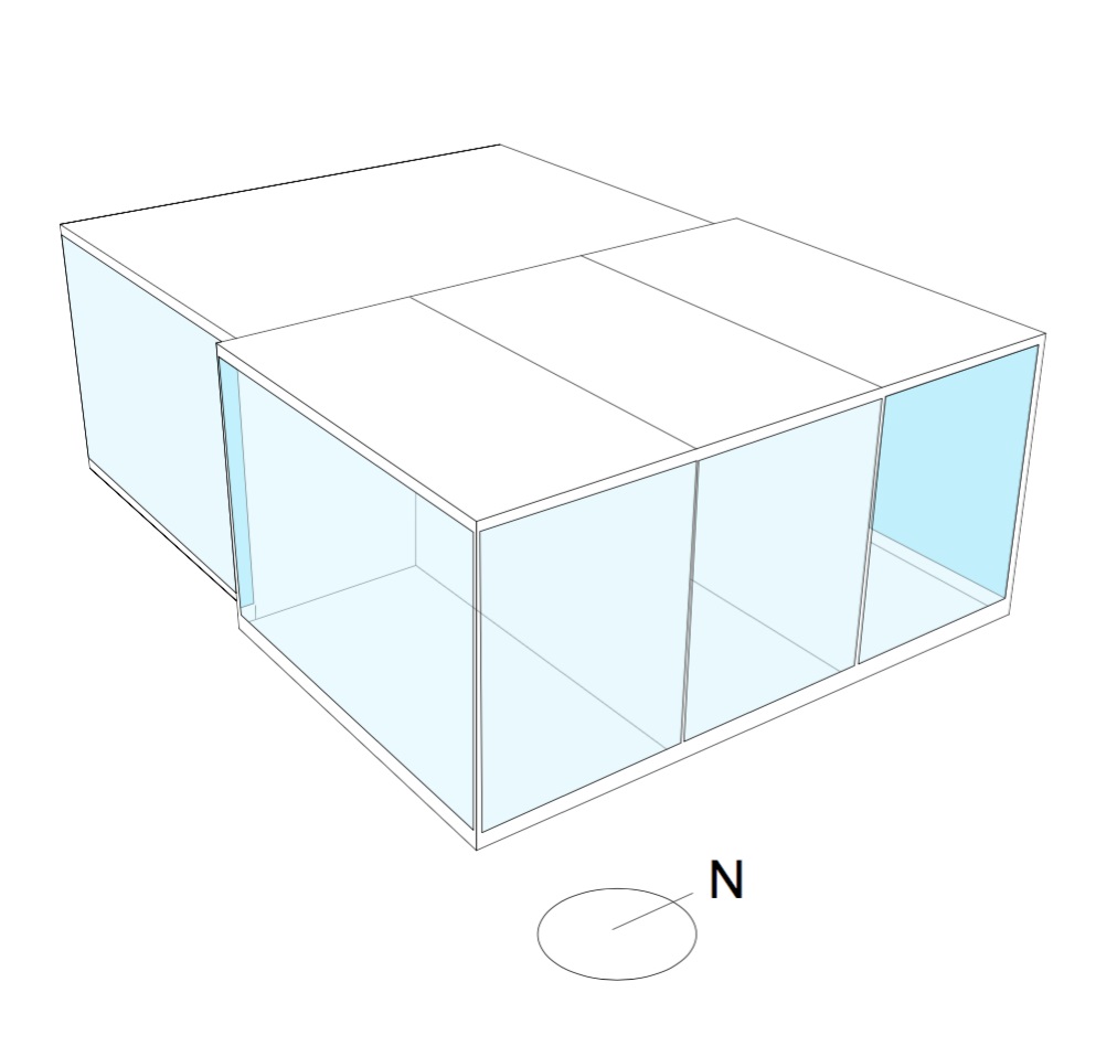
Axonometric View
Figure 2
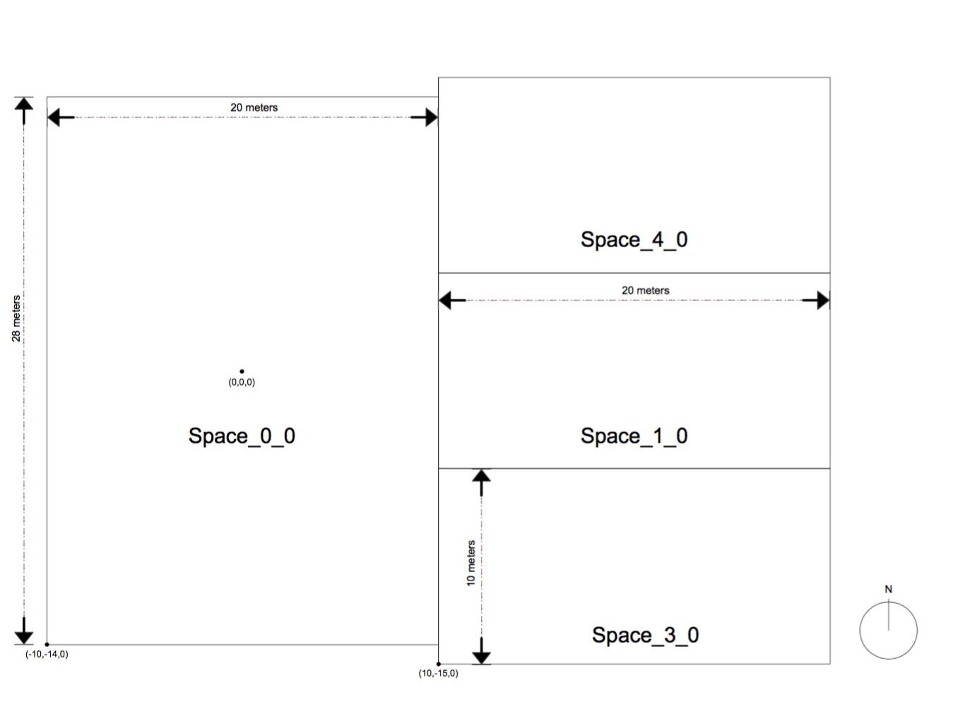
1st Floor Plan View
Figure 3
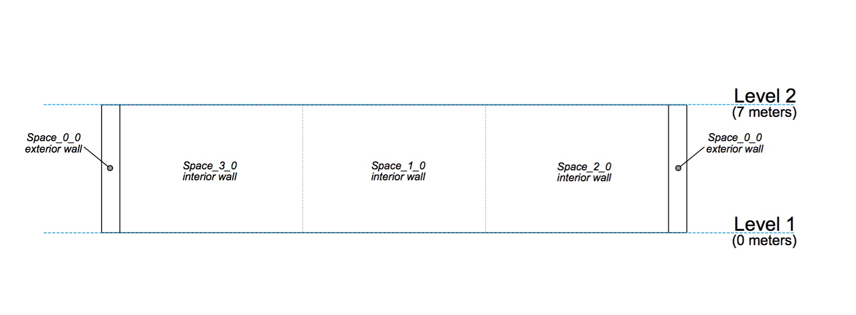
Section Looking North
Figure 2 shows a plan view of the first floor, at a height of 3m above height z=0.
Figure 3 shows a section cut through the three single height spaces, where the section cut positions the user at the eastern side of the building looking west. The cut takes place at x=20m.
Using these three images, it should be possible to reconstruct this test case in the vendor tool of choice and submit this test case to gbXML for validation towards Level 1 or 2 certification.
Click
here for the test case PDF document.